Hookup guides
Multiplexers
Connecting multiple buttons to a microcontroller can be a challenge, especially when dealing with a large number of inputs. A multiplexer offers an efficient solution by allowing up to 16 buttons to be interfaced with just a single pin (and a few channel switching pins). This guide will walk you through the process of hooking up buttons to the CD74HC4067, making it easier to expand your project without needing additional pins on your microcontroller.
Parts required
- An Arduino Uno (or any other Arduino-compatible board)
- 2x momentary switch / button
- 1x 16 channel CD74HC4067 multiplexer
- A solderless breadboard
- Some jumper wires (male to male)
Instructions
The multiplexer has 8 pins to consider:
- VCC - the supply voltage input pin
- GND - the ground connection pin
- EN - pin for enabling/disabling the mux (pulling it LOW enables it / pulling it HIGH disables it)
- S0, S1, S2, and S3 are address selection pins used to specify which channel to connect to.
- SIG - the signal input/output pin
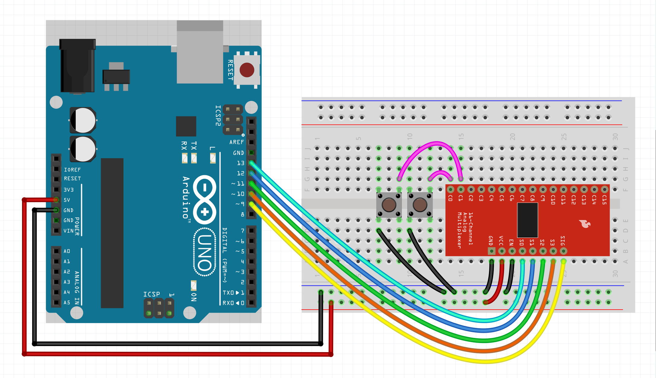
Now hook up the components according to the figure below.
As your circuit grows in complexity, adding a decoupling capacitor across the VCC and GND pins becomes increasingly important. This capacitor serves to stabilize the voltage supply, reduce noise, and improve overall performance and reliability. In this case you could start with a 100nF (0.1 µF) capacitor. Put it as close as possible to the VCC and GND pin of the multiplexer. If that is not enough you can go up to something like 1µF (if you are dealing with a very noisy system). Note that going up in capacitance comes with trade-offs such as increased component size, cost, and potential impact on circuit response time.
Example code
We will assume you know how to use the Arduino IDE and upload your sketches to a board. If not, have a look at the tutorials at: https://www.arduino.cc/guide
Also make sure you have the CTRL library installed through the library manager.
NOTE: Make sure to check the datasheet of your multiplexer to determine if the default 1 microsecond switching interval is sufficient. For example, a Sparkfun CD74HC4067 running at 5 volts will probably operate fine at a switching speed of 1 microsecond. However, if you run it at 3.3 volts, it will need a switching interval of around 2 microseconds or higher. You can set this with: mux.setSwitchInterval(2). There are, however, more factors that determine how responsive your MUX is, such as signal integrity and power supply noise. Always add some decoupling capacitors to your MUX power supply and at any other place where noise might be created.
Then upload the sketch to your board and open up the serial monitor. This allows you to see the output of the button presses. For some boards you have to set the 'USB Type' to 'Serial', in the Arduino IDE under 'Tools'.
P.S. You can easily adapt this guide to work for potentiometers and rotary encoders. Just create a bunch of potentiometers or rotary encoders and pass a reference of the multiplexer to them (&mux).
#include <CtrlMux.h>
#include <CtrlBtn.h>
// Create a multiplexer object. With:
// The signal pin, s0, s1, s2 & s3 (optional).
CtrlMux mux(9, 13, 12, 11, 10);
// Define an onPress handler for button 1.
void onPress1() {
Serial.println("Button 1 pressed");
}
// Define an onPress handler for button 2.
void onPress2() {
Serial.println("Button 2 pressed");
}
// Create two buttons. With the: signal pin number (corresponds to the attached channel on the multiplexer),
// the bounce duration, an onPress handler, without onRelease handler, without onDelayedRelease handler
// (we don't need them for this example) & a reference (&mux) to the multiplexer.
CtrlBtn button1(0, 15, onPress1, nullptr, nullptr, &mux);
CtrlBtn button2(1, 15, onPress2, nullptr, nullptr, &mux);
void setup() {
Serial.begin(9600);
mux.setSwitchInterval(2); // In microseconds.
}
void loop() {
// The process methods will poll the button objects and handle all their functionality.
mux.process();
}