Hookup guides
Rotary encoders
In this guide, we will walk you through the process of connecting an incremental rotary encoder with quadrature output to an Arduino UNO. Rotary encoders are commonly used for precise control in various applications, such as volume knobs, motor control, and user interfaces. They are also less susceptible to electronic noise compared to potentiometers, making them an excellent choice for many projects.
The CTRL library already provides some (out of the box) filtering / debouncing of the encoder signal, but additionally we will implement a filter circuit to improve signal reliability and show you how to use the CTRL library to handle the encoder input efficiently.
A good-quality rotary encoder option is the Bourns PEC11R. This mechanical encoder works well with our setup, but you can also use other types of encoders, such as optical or magnetic. These alternatives will function seamlessly as long as they have a quadrature output.
Parts required
- An Arduino Uno (or any other Arduino-compatible board)
- 1x Incremental rotary encoder (with quadrature output)
- 2x 0.1uF (100nF) capacitors (ceramic & non polarized)
- 2x 10 kΩ resistors
- A solderless breadboard
- Some jumper wires (male to male)
Instructions
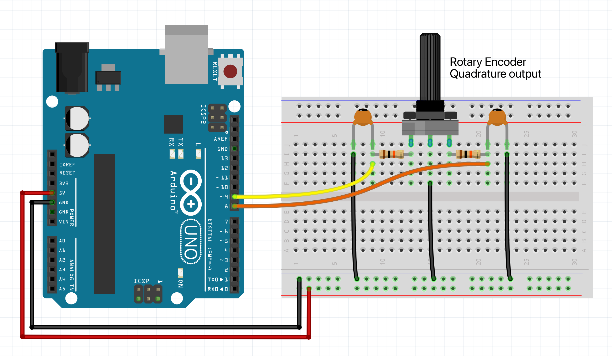
The rotary encoder has 3 pins: terminal A (which is usually the CLK pin), terminal B (usually the DT pin) & terminal C (normally goes to ground). Be sure to check the schematics of your encoder, to confirm this. Next connect all wires and components as shown in the figure below.
Example code
We will assume you know how to use the Arduino IDE and upload your sketches to a board. If not, have a look at the tutorials at: https://www.arduino.cc/guide
Also make sure you have the CTRL library installed through the library manager.
NOTE: Then upload the sketch to your board and open up the serial monitor. This allows you to see the output of the encoder turning. For some boards you have to set the 'USB Type' to 'Serial', in the Arduino IDE under 'Tools'.
#include <CtrlEnc.h>
// Define an onTurnleft handler.
void onTurnleft() {
Serial.println("Turn left");
}
// Define an onTurnRight handler.
void onTurnRight() {
Serial.println("Turn right");
}
// Create a rotary encoder with the clk signal pin number, dt signal pin,
// onTurnleft & onTurnRight handler.
CtrlEnc encoder(9, 8, onTurnleft, onTurnRight);
void setup() {
Serial.begin(9600);
// In this example we use a board that has internal pull-up resistors (most do). So
// you don't need to call the setPinMode() method, because the software is set to
// 'INPUT_PULLUP' by default. However, if your board does not support this, you
// can opt to use an external pull-up resistor and set the pinMode accordingly:
// encoder.setPinMode(INPUT, PULL_UP);
// If you want to use a pull-down configuration and have a board that has internal
// pull-down resistors, you can do this:
// encoder.setPinMode(INPUT_PULLDOWN);
// If you want to use a pull-down configuration but your board does NOT have internal
// pull-down resistors, hook up your own resistors and use this:
// encoder.setPinMode(INPUT, PULL_DOWN);
}
void loop() {
// The process method will poll the rotary encoder object and handle all it's functionality.
encoder.process();
}
Final thoughts
If you prefer not to build your own filter circuit, you can opt for an encoder like the KY-040, which comes with a built-in filter and a switch. This allows you to skip connecting the capacitors and resistors as described in the instructions above, and connect it directly. However, be aware that the quality of these encoders is often lower, as they are typically inexpensive. So yeah... take your pick, have fun hooking it up, and hopefully you'll be able to make some awesome stuff :)