Hookup guides
Potentiometers
Potentiometers are versatile components commonly used in electronics to adjust levels, such as volume, brightness, and position. They are variable resistors that can provide a range of resistance values by rotating a knob or sliding a lever. In this guide, we will walk you through the steps to connect a potentiometer to an Arduino and read its values.
When dealing with potentiometers, we are working with analog signals. Unlike digital signals, which have discrete values, analog signals vary continuously. This makes potentiometers more sensitive and susceptible to electrical noise compared to buttons and rotary encoders. Proper wiring and shielding can help minimize noise interference.
The CTRL library already provides some (out of the box) filtering to stabilize the readings of a potentiometer through a process called 'exponential smoothing.' This technique helps to smooth out rapid fluctuations in the data, making the readings more stable and reliable. However, there can be other factors that cause unwanted readings. We will talk more about this in the instructions below.
Parts required
- An Arduino Uno (or any other Arduino-compatible board)
- 1x 10 kΩ linear potentiometer
- 1x 10nF (up to 100nF) capacitor (ceramic & non polarized)
- A solderless breadboard
- Some jumper wires (male to male)
Instructions
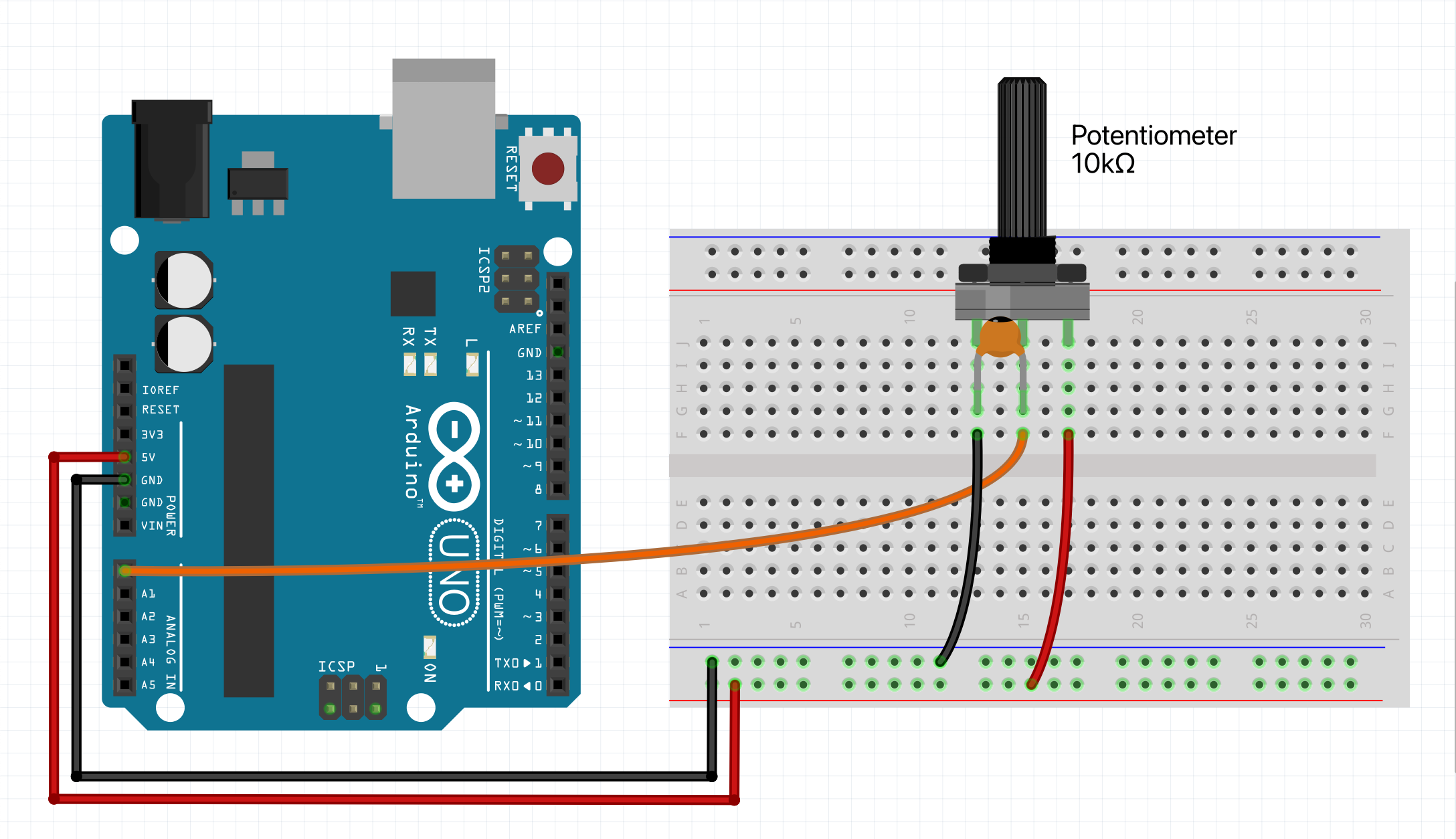
Connect the outer legs of the potentiometer to the ground and power rail. The middle pin, usually the 'wiper', will send the signal to the Arduino. Verify your potentiometer’s specifications to confirm the pin functions. Connect the wiper to analog pin 0 (A0).
Include a decoupling capacitor between the wiper and ground to reduce electrical noise. Start with a 10nF capacitor and increase the value if necessary (since there is only one input device in this circuit, it will not matter). However, note that higher capacitance will make the potentiometer less responsive.
If you have motorized components in your circuit, they can introduce significant noise. To mitigate this, place capacitors across the motor’s power supply, use twisted pairs for the signal and ground wires to the potentiometer, and for the motor power leads. Also, avoid running the potentiometer’s twisted pair too close and parallel to the motor power leads (or any other source of high frequency interference).
A good practice is to utilize separate ground (and power) rails to separate analog inputs from digital ones (most boards have multiple ground and power pins). Connect the analog potentiometers, to a dedicated analog ground (and power rail), while the digital components (buttons & rotary encoders) should be connected to a separate digital ground (and power rail). This separation helps to reduce interference from digital switching noise.
Another factor is mechanical instability. If the potentiometer is not securely mounted (breadboards are notoriously known for causing noisy connections), any slight movement or vibration can affect the resistance and, consequently, the readings. Ensuring that the potentiometer is firmly fixed in place can help maintain consistent measurements.
Example code
We will assume you know how to use the Arduino IDE and upload your sketches to a board. If not, have a look at the tutorials at: https://www.arduino.cc/guide
Also make sure you have the CTRL library installed through the library manager.
NOTE: Then upload the sketch to your board and open up the serial monitor. This allows you to see the output value of the potentiometer. For some boards you have to set the 'USB Type' to 'Serial', in the Arduino IDE under 'Tools'.
#include <CtrlPot.h>
// Define an onValueChange handler
void onValueChange(int value) {
Serial.print("Output value: ");
Serial.println(value);
}
// Create a potentiometer with the pin number, max. output value,
// sensitivity margin (can be 0.01 to 100) & onValueChange handler.
CtrlPot potentiometer(A0, 100, 10, onValueChange);
void setup() {
Serial.begin(9600);
}
void loop() {
// Handle all potentiometer functionality.
potentiometer.process();
}